|
|
|||||||||
|
| Contact |
| Jana 76 |


|
|
Jana 76 - HP Installation Guide |
|
OVERVIEW
To begin with this installation is not suggested to be done by a 1st time Ring and pinion Installer. I would suggest a minimum of 4 ring & pinion set-ups experience prior to doing this modification. This kit is designed to be installed without machine work if all the proper parts are purchased. Good metal fabrication skills are a must. If you do not have a collection of bearing pullers, drivers, grinders, micrometers, dummy bearings, press, torch, welder, vice etc. you probably should not be doing this job.
NOTE: This is just not one of those "do-it late Friday night to go wheeling Saturday morning jobs". This Kit is designed to work with Stock Dana 60 standard housings and Dana 70, & 70U standard parts. Other manufactures' parts may require machine work. Also if you are used to doing a set up in 3-4 hours, then plan double or triple time.
I as much as you, hate instructions that are either too detailed or not detailed enough. Generally I want to see a good picture and the basics and I'll get right to it; however there are some steps in this conversion that must be done in the correct order or bearings and seals will be permanently destroyed. Now, I know you don't want to review 16 pages of procedures to find two torque specs and a couple of critical dimensions. So I will provide a Three step set of instructions, 1st I will give an overview of operations, 2nd detail it all, and the reasons things are done in such order & some hints, and 3rd a check list so you can go along and not paint yourself in a corner, or more importantly discover you have to grind something and the only way to prevent getting grit into your new bearings & locker will be to completely disassemble the unit wasting hours of rework & clean up time.
The basic order of operations will be to:
- Grinding the housing for ring gear clearance.
- Grind the carrier bearing snout to clear a narrower bearing.
- Differential cover reforming and clean up.
- Partial pinion set up, Installing adapter bearings, & spacers, no seal
- Carrier & ring gear set up, with adapter bearings & spacer
- Gear pattern and carrier bearing preloads
- Pinion preload setting
- Seal and seal ring, with final install of pinion with seal
- Ring gear final install
- Install cover oil, etc.
- Break-in
(1) Grinding the housing
-
After removing all old D60 parts reinstall just the d60 ring gear on the D60 carrier with just 4
bolts, and reinstall.
Note: If you are going lower gears you can put washers between your carrier and your old ring gear to simulate the thickness of your new gear, and you can also add an 1/8" thick lock washer to simulate a low speed carrier if your carrier is high speed.
Hints: At this point I can't emphasize enough that having a set of dummy carrier bearings will save an immense amount of time, energy, and frustration. And I would not attempt to do an ARB without a dummy carrier to get you gear set up before fighting all that weight in and out. Beg or borrow an open carrier to use as a dummy carrier.
-
If you don't have dummy bearings a set can be made out of your old bearings by sanding or
honing the insides out until the bearings glide on and off of the carrier bearing snouts. Glide
means that you can slip it on and off by hand, but it would not fall off under its own weight, thus
there is no clearance or play when slipped on. This can also be done with a hardware store flap
wheel sander in a drill. I usually sand around evenly for a minute and then check for fit,
repeating this step 3 to 10 or more times until I get the perfect slip fit. If your old bearings are
worn a few thousands or are slightly different dimensionally you can adjust later with the new
bearings and shims, at least you will be very close as you move towards final assembly.
Note: When using dummy bearings pull out a .010" shim from each side of the carrier, this removes preload making the carrier easy to take in and out.
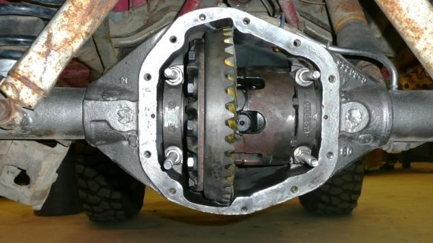
- Place the D60 carrier assembly into the housing. You will notice that there is about 1/4" space all around it. Since the D70 gear is 3/4" larger in diameter you need 3/8" space all around it. Thus you will be grinding approximately 1/8" into the housing. The housing will clear the larger ring gear most the way around except at the very top, bottom, and front near pinion head bearing.
-
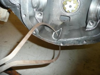
Using the supplied 3/8" ball on a stick feeler gauge, dip it in gear marking compound, grease or
paint then place it on the outside of the ring gear and it will leave a trail where you need to
grind for top and bottom clearance. Then since you won't be able to exactly see what you need
at the front, mark out each side of the ring gear, you will grind the housing down between these
marks until the chamfer is gone for the pinion bearing, and about half of the cast in oil scraper.
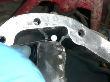
Marking Areas to grind -
Remove carrier
Safety: In the next step you could breathe in enough cast iron dust to make your nose bleed, this is normal and you will recover but it's certainly not necessary. I highly recommend a dust mask or at least a handkerchief over your nose. Ear protection is also a must.
Safety: A full face grinding shield must be worn with goggles to protect your eyes. The wind created by a 4.5" angle grinder in the housing will hurl the grit right at your face.
- Take your time grind a little bit then reinstall carrier and using feeler gauge continue to mark and grind until you can tape the loose 3/8" ball anywhere on the OD of the ring gear and spin it and see about a 1/32 -1/16" clearance. At this point the D70 gear would be able to spin in the housing however it would not go in.
-
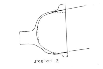
You now have to clear the housing tangent to the top and bottom clearance grinds to allow the
D70 gear to fit in. These tangent lines are not perpendicular to the cover surface; they rise
upwards about 1/4", Use the dimension from sketch 1 and sketch 2 to scribe a line at the top of
the housing.
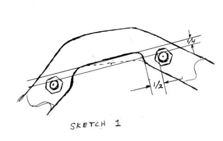
Note: you will remove most of the material at the top of the housing keeping the bottom as thick as possible. Thus the ring gear is installed slightly above center line of axle and rolls down into the clearance pocket at the bottom of the diff.
-
Use the D70 gear not installed on a carrier to start this part of the grinding procedure, once you
can get it in by itself then we take a break, and clean the cast iron dust from our nostrils.
Note: there will probably be more grinding to actually fit the D70 parts in as an assembly but this way you can work your way to the proper clearances without over grinding.
-
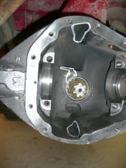
Check housing thickness with a caliper) you will get a small area at the bottom of the ring gear,
about the size of an elongated quarter that is only 1/8" thick. This probably will not be a
problem for a set of 4.56 gears but was with the thicker 5.86 gears.
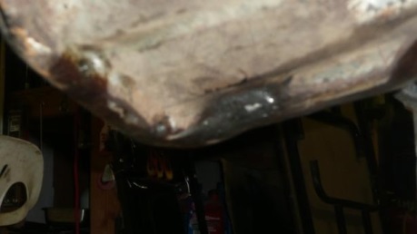
Checking Thickness Weld Buildup Note: Castings always vary a bit so if it gets thin it can be built back up to a minimum of 1/4"on the outside using a few passes with a wire feed welder. The housing is made of nodular cast Iron and welds nicely, but I still weld only 1" stringer beads at a time using the back stitch method and peen each stringer while still red with a small ball peen hammer to prevent any cracking. Don't get in a huff over losing ground clearance as this build up area will not be at the housings lowest point.
(2) Grinding the carrier
You will be placing a thin race and spacer assembly onto one side of the D70 carrier to get correct spacing.
Now this gets rather interesting as you will need a D70 or D70U Carrier, but it does not matter whether or not it is a high or a low speed. Although the carrier offsets are the same amount on a D60 & D70 (1/8") the actual placement on the carrier is about 1/16" different. Thus by using a thinner bearing on one side of the D70 carrier and a thicker shim stack on the other side you can move it side to side quite a bit.
Note: A D70HD carrier could be used for this adaption but it would require machining the bearing journals down to the D60 carrier bearing size.
Note: 70HD carriers can be used but require grinding to shorten the bearing snout to D60 length.
-
Low on Low
If you are putting a Low speed Ring and pinion on a low speed carrier the flange on the carrier will be too close to the pinion thus a thin race and spacer is used on the ring gear side of the carrier and a thick shim stack is used on the pinion side of the carrier to move the flange away from the pinion.
-
Low on High
If you are putting a low speed Ring and pinion on a high speed carrier the flange on the carrier will be too far away from the pinion thus a thin race and spacer is used on the pinion side of the carrier and a thick shim stack is used on the ring gear side of the carrier to move the flange towards the pinion.
-
High on high
If you are putting a high speed Ring and pinion on a high speed carrier the flange on the carrier will be too close to the pinion thus a thin race and spacer is used on the ring gear side of the carrier and a thick shim stack is used on the pinion side of the carrier to move the flange away from the pinion.
-
High on low
Difficult but possible. Bearings will be placed as in High on High but you will also have to have a good machinist remove an 1/8" off of the Ring gear side bearing register or take 1/16" of the ring gear side bearing register and 1/16" off the ring gear mounting face. Also the housing and or carrier ribbing may need to be ground more to clear the side of the carrier on the ring gear side. Less grinding is required when doing the 1/16" & 1/16" machining process, but make sure ring gear bolts do not bottom out after removing 1/16" of material from carrier flange.
Now since the above was rather confusing here is sketch that's worth a thousand words.
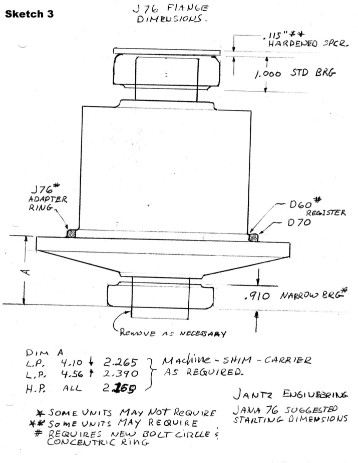
|
Now the title of this section was grinding the carrier.
- So after deciding which of the ring gear carrier combinations you will be using grind about 1/16" off of the carrier bearing snout on the side that the thin bearing assembly will be going onto such that it does not protrude beyond the outer bearing race and shim assembly. If you grind the snout till the original chamfer disappears it should be sufficient. The next hint is a Dummy carrier. If you are installing a Powerlock, or a Detroit and especially any Selectable locker, fighting the weight and complexity of these things will wear you out. Use a dummy carrier to get the basic ring a pinion set up done. It is worth while removing the spider gears and cross pins such that you save weight as well. You can even get the basic gear set up using an open High speed carrier, and then at the very end of all these steps put in your low speed locker for final assembly by switching the thin bearing assembly from side to side.
- Now it's time to try and install the gear on the carrier and see if you can actually get it in the housing. But first you'll want to just put the dummy carrier in the housing without a ring gear to establish the approximate shim pack starting thickness by installing the dummy bearings (with thick and thin races & the .100 thick spacer) on appropriate sides, Leave all shims out from under bearing on pinion side and place about .090" under bearing on gear side. Slip dummy carrier set up into housing, pry to one side and place a stack of shims in the gap between the race and the housing. Then remove carrier and place this shim stack under the ring gear side dummy bearing. Then test fit assembly into housing. At this point you don't want any bearing preload, so can you slip it in and out many times for fitment. Add or remove shims until you get a slip fit. I usually put enough shims in so that it just taps in and I can almost pull it out by hand.
- Now install the ring gear with just 4 bolts lightly torqued. Then place assembly into housing, Grind clearances again if/as necessary. Clearance should be checked with the ring gear positioned all the way to the max in each direction. To do this place all the shims on one side of the carrier only then check for clearance then switch all the shims to the other side and check for clearance. Note you may have to clearance the side of the carrier ribs, and or housing so that the carrier does not run into the side the housing.
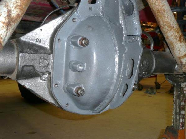
(3) Differential cover
Now you have grinding grit all over everything. But don't worry about clean up yet. Spraying a bit of paint on the inside of the cover place the cover on with 4 evenly spaced cover bolts about 2 threads screwed in. then spin the ring gear through the pinion hole and press the cover against the gear. The scratches in the paint will show the interference area. Transfer this area with marks onto the outside of the cover.
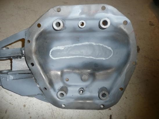
|
| AREA MODIFIED FOR RING GEAR CLEARANCE |
Note: the following is best performed with two people.
- Remove the carrier. Bolt the cover back on with all bolts tight. Heat up the area to be clearanced with a torch redish orange, then using a stout rod with a slightly rounded end beat out the cover through the pinion hole for ring gear clearance.
-
After cover cools to room temp, remove it, replace carrier assy. back in and verify you have ring
gear clearance. Repeat heat and beat steps if necessary.
Note: if you have an aftermarket cover, cutting sectioning and welding may be necessary
(4) Partial pinion set up
Install pinion tail bearing cup spacer with large beveled side against shoulder, then install tail bearing cup. (If you have an old used Pinion tail bearing cone now would be a good time turn it into a dummy bearing).
Note: The Jana kit moves the pinion depth shims from the OEM location between the pinion cup and housing bore to between the pinion cone and pinion head (similar to 10 and 12 bolt Chevy set ups).
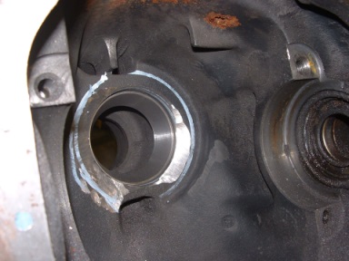
Next we make room for the Stepped pinion race to sit deeper into the housing.
Referring to sketch 4; Use provided gauge/scribe and lay out a guide circle to grind to.
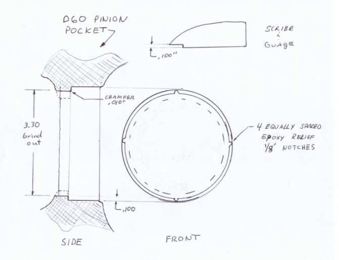
|
Darken pinion pocket shoulder with layout dye or black sharpie to improve visibility. Die grind shoulder to edge of scribed circle. Be careful when grinding to NOT nick the pinion bore or shoulder. You are just making clearance for the step portion of the pinion bearing to drop into. Use .100 step in gauge to verify depth. Housing casting must not touch stepped edge of gauge.
- Clearance for housing bore is 3.300" plus
- Step in race is machined to 3.295" giving .005" clearance.
When gauge goes completely around original bore without touching the housing casting you are ready to do a check fit. Using a black sharpie, darken the stepped area of the pinion race. Install the race and remove it. Check for any interference marks and clearance if/as necessary.
Note: Very carefully tap race into Pinion pocket, be very careful to go in evenly as the radius is not as generous as the factory bearing and will shave into the pocket wall if not installed straight.
After removing the race, check to see if any of the black sharpie was rubbed off the stepped area. If any of the sharpie mark is gone, this indicates an interference fit. Find corresponding area and regrind and then check the fit again until you have clearance.
Now I don't expect anyone other than a few tool & die makers to be able to grind within .005" So we will fill in the gap with epoxy having nearly the same compressive strength as cast Iron.
Now I get a lot of questions about this step and is it going to cause some trouble? Well I've tested this set up to breakage without epoxy and where it broke was not near the epoxyied area, so it's probably not even necessary. On the other hand, I have seen stock bearings spun in housings so everything we can do to assure reliability is going to get done.
Grind (4) 1/16" equally spaced notches in shoulder. (Or cut 1/16" 'V' with hack saw blade.) These notches provide a relief for excess epoxy to squeeze out so as not to effect pinion depth. Deburr edge of step with sand paper leaving slight chamfer .010".
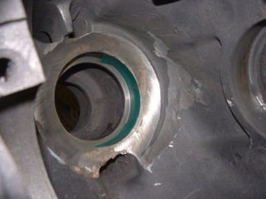
Clean housing thoroughly and prep for final race install. Have all tools necessary for the next steps laid out and ready to go prior to mixing epoxy!! As you only have about 5 minutes to assemble! Mix epoxy, thoroughly.
Place a smooth thin layer completely around each mating surface, both the step on the bearing and the ground out bore of the housing. Cover surfaces but do not use excessive amount. No epoxy is necessary in the original housing bore or on the original race OD.
When the race is in about 90% to 95% , wipe out any excess epoxy, then Take the pinion with well greased bearings on it and install it with the tail bearing and yoke. This is best done with a Dummy Pinion Cone as it will be removed later several times while setting the correct pinion depth.
Note: this new design places the pinion depth shims between the head of the pinion and the pinion bearing instead of between the pinion race and housing.
Note: Due to clearance issues this system does not use any baffles, but it does use the beveled slinger.
Note: You need a temporary spacer to enable the bearings to be tightened up. Place the 1/8" thick three internally tabbed spacer between the tail bearing and yoke. Also use the supplied non locking pinion nut for trial assembly so as not to wear out the locking pinion nut.
Note: This spacer is used in a factory set up but not used with the Jana kit except for this purpose as a temporary spacer.
Torque down till you cannot rotate the pinion with one hand but you can rotate it with two hands.
Using a large center punch in the center of the pinion gear, drive the head down with a couple of hard blow with a large hammer. If the pinion now rotates you squeezed a little more epoxy out from behind the shoulder, repeat torque and hammer steps until bearing race is fully seated. Take a 20 minute break while epoxy cures then disassemble and clean off excess epoxy.
Warning: do not install the seal, pinion bearing preload shims or seal ring at this time or you will just ruin them.
- Install the beveled Slinger onto the pinion shaft, and press on pinion head bearing. Place pinion in hole and mark around as pictured. This is the lay out for the grinding necessary to clear the beveled pinion. Then place 3/4" wide tape into pinion bearing hole to simulate the width of the pinion bearing as pictured, grind from this depth out approximately 15 degrees to clear for beveled slinger. Use liberal amounts of gear marking compound on the back of the slinger to mark and grind for clearance as pictured. Grind until you can install the pinion, and rotate pinion without the slinger touching housing ,then you are ready to do a partial pinion set up. Now is the time to clean everything up like you were going to assemble an engine.
- Place a .020" shim stack between the slinger & bearing to set your initial pinion depth
and partial pinion set up. Install pinion with no preload shims and just snug up the
pinion nut for some slight preload. This will be the starting depth for setting up the ring
High Pinion clearance marking High Pinion bearing simulation 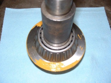
High Pinion gear marking compound for clearance grinding 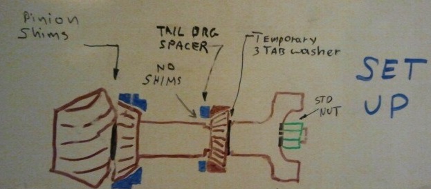
(5) Carrier
- Install as typical of any ring pinion set up. I suggest removing all the shims out from under the dummy bearings. But keep track of the total shim pack. Place the ring gear side dummy bearing all the way on, then the pinion side dummy bearing 3/4s the way on. While installing carrier pry the dummy bearings outboard, and simultaneously pry the ring gear till it just touches the pinion then
- Take your shim pack and divide it up side to side between the bearings and the carrier for a preliminary back lash and preload setting.
(6) Gear Pattern
- For this step, set up the ring and pinion as you would normally do, shimming the pinion in or out for correct gear wear pattern keeping the back lash in specs.
- Don't worry about pinion preload shims yet but keep nut tightened for proper pinion bearing preload.
- Once you are happy with the pattern, remove the dummy carrier and install your Locker with the dummy bearings to get the backlash correct again, and then switch to the final bearings setting your carrier preload. Dam that thing is heavy! Then unfortunately remove it again and set it aside.
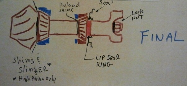
(7) Pinion Preload setting
Note: In order to keep from snapping D70 pinion shafts off at the shoulder where the preload shims go, the radius was increased; unfortunately the bearings available have a smaller radius. To remedy this issue Dana used an 1/8" thick pinion preload spacer formed with a large radius so as not to ride up the radius at the shoulder. This 1/8" spacer is not used here for space reasons but its function must be kept. (Well be did use it earlier for a temporary spacer but will not use it for final install)
- Install the chamfered .030" shim on first with chamfer to radius.
Warning: This shim must always be placed in shim pack 1st with chamfer to radius or failure will occur.
- After installing modified 1st shim, add about .025" more shims and use this as a starting point to set up the correct Pinion preload. Add and subtract shims until torque to rotate pinion is between 17-30 in-lbs. Remember to use the plain nut with and a washer, with the three tabbed spacer temporarily placed between the yoke & tail bearing.
(8) Seal and seal ring final install
|
- Remove Pinion yoke, & 3 tabbed spacer.
- Install seal,
- Install seal ring, through seal flush against tail bearing with suitable driver. Be extremely careful with the outside diameter of this ring as the inner Oil lip seal rides on it. The outer seal lip rides on your pinion yoke just past the chamfer. Make sure this area is free from nicks, and polish.
- Install yoke, using only 1 washer, a new pinion nut & torque to 240-300 ft-lbs.
(9) Ring & carrier Final install
Install as normal
|
(10). Cover Install
Install cover
Note: Add break-in oil. I recommend using standard 90wt GL5 for the 500 mile break-in period then Amsoil severe gear 75W140 (SVT) for general use, or Severe Gear 250 (SRT) for rock crawling and desert racing. If you didn't purchase this with the kit it can be ordered at http://www.amsoil.com/ search for SVT or SRT and use sponsoring dealer number # 1704698 at checkout. Typically arrives in 1-2 days.
|
(11) Break in
Follow standard break in procedures, 500 miles before hard use and never more than 25 miles at a time without a 15 min cool down.
Note: for a good dissertation on break in procedures please go to New Gear Break-In.
(12). You are now JANA HYGRADED
Now go out and wheel it like you stole it and enjoy the strength of the JANA HYGRADE
CHECKLIST
- Grinding the housing
- Install just the d60 ring gear on the D60 carrier with just 4 bolts.
- Make dummy bearings
- Place the D60 carrier assembly into the housing.
- Mark out where you need to grind for clearance. see picture.
- Remove carrier
- Grind a little bit then reinstall carrier and using feeler gauge continue to mark and grind until you can tape the loose 3/8" ball anywhere on the OD of the ring gear and spin it and see about a 1/32 -1/16" clearance
- Clear the housing tangent to the top and bottom clearance grinds to allow the D70 gear to fit in. sketch 1 & 2.
- Use the D70 gear not installed on a carrier for check fits for this part of the grinding procedure.
- Check housing thickness with a caliper (see photo) build up to 1/4" with weld if necessary.
-
Grinding the carrier
- Grind about 1/16" off of the D70 carrier bearing snout on the side that the thin bearing assembly will be going onto.
- Determine approximate shim stack with dummy bearings.
- Install ring gear on dummy carrier and check, fit and grind clearance again if/as necessary.
-
Differential cover
- Spray paint on the inside of the cover & mark for ring gear clearance. Transfer this area with marks onto the outside of the cover.
- Remove the carrier. Bolt the cover back on with all bolts tight.
- Heat & beat & clearance cover.
-
Partial pinion set up
- Clean up & reorganize your bench.
Note: Due to clearance issues this system does not use any baffles, just the slinger.
- grind housing using scribe / guage for clearance of the stepped bearing.
- Check fit stepped pinion race
- epoxy race in place.
- Assemble bearings on pinion as usual and install into housing with yoke and 3 tabbed space between yoke & tail bearing.
-
Grinding for beveled slinger (High Pinion Installs only)
Warning: do not install the seal, pinion bearing preload shims or seal ring at this time or you will just ruin them.
- Reinstall Pinion with 0.020" shim pack between slinger & head bearing. Tighten the pinion nut until you are close to proper pinion preload. This is close enough for a starting point to install ring gear and get the pattern set up.
- Clean up & reorganize your bench.
-
Carrier
- Install as typical of any ring pinion set up.
- Set preliminary back lash and preload setting.
-
Gear Pattern
- Set up the ring and pinion as you would normally do, for correct pattern & backlash
- No preload shims yet but keep nut tightened for proper pinion bearing preload.
- Remove the dummy carrier and install your Locker with the dummy bearings to get the backlash correct again,
- Switch to the final bearings setting your carrier preload.
- Remove carrier and set it aside.
-
Pinion Preload setting
- Install the chamfered .030" shim on first with chamfer to radius.
Warning: This shim must always be placed in shim pack 1st with chamfer to radius or failure will occur.
- After installing chamfered 1st shim, add about .025" more shims and use this as a starting point to set up the correct Pinion preload. Add and subtract shims until torque to rotate pinion is between 17-30 in-lbs. Remember to use the 3 tabbed temporary spacer between yoke & pinion tail bearing.
The following steps must be done in exact order to prevent seal damage.
- Remove Pinion yoke, & 3 tabbed temp spacer.
- Install seal
- THEN Install seal ring, ( 1 1/4" id X 1 7/8" OD x 1/4" thk washer) through seal flush against tail bearing with suitable driver. Be extremely careful with the outside diameter of this ring as the inner Oil lip seal rides on it. The outer dust seal lip rides on your pinion yoke just past the chamfer. Make sure this area I free from nicks, and polish.
- Install yoke, using a new pinion nut & torque to 240-300 ft-lbs.
Install as normal
- Install cover
- Add oil. I recommend Amsoil severe gear 75W140 for general use, and Severe gear 250 for rock crawling and desert racing.
Follow standard break in procedures, 500 miles before hard use. Yeah, like that ever happens.
Please Note: When you move the differential for the Jana kits it can move from 1/8" to 1/4" to the left. While you are installing the axle on that side, make sure the yoke of the axle can be pushed all the way into the axle tube. If it can't just grind a little off.
Copyright Jantz Engineering, All rights reserved.
|